FLUID TRANSPORT
Samplers are basically smart pumps. There are two ways that the fluid can be moved from a source to a bottle (destination).
- Fluid can be “pulled” by creating suction (vacuum) in the tube. The fluid will enter the tube to replace the air that was removed. It is pushed into the tube because removing air lowers the pressure in the tube and atmospheric pressure outside the tube is greater causing water to flow into the tube. The pull method is physically limited in total vertical height. An optimal height is approximately 20 feet. Samplers can pull higher but performance degrades. The higher the water is pulled the less pressure difference there is so water enters the tube slower and the transport velocity slows down. This is true regardless of what sampler or device is pulling the water up. Other negative affects such as out-gassing of air in the fluid can slow the transport even more. A fluid can be pulled horizontally a greater distance than it can be lifted vertically. Both Vacuum and Peristaltic samplers use the pull method to collect a sample. Pumps can be placed at the source to push water to the sampler, assisting it in taking a sample.


VACUUM
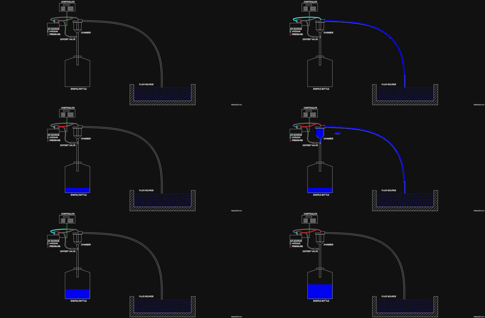
A vacuum sampler uses a vacuum compressor to create the vacuum and pressure that move fluid. A chamber is used to measure the desired volume of the fluid. The compressor pushes air into the chamber, which pushes air out the intake line purging the system. Air is then pulled out of the chamber causing the source fluid to flow in the intake hose to the chamber. Methods vary at this point. Manning samplers fill the chamber to full even if this is past the desired volume. Once the chamber is full the compressor measures the sample by pushing air into the chamber and forcing liquid out till the level reaches the desired volume at which point the liquid has dropped below the exit point so fluid is not longer pushed out. After measuring the sampler opens the discharge tube and the sample is deposited in the destination bottle. The fluid doesn’t go through the compressor.
ADVANTAGES
Volume repeatability. The sample is a true measured volume. Regardless of head height, bubbles or other factors, the amount of fluid that remains in the chamber is the same. See Myths below for information about chamber cross contamination.
- Transport velocity. The EPA recommendation for transport velocity is 2-10 ft per second, faster being better. Vacuum samplers can achieve transport velocities in excess of 5.5 feet per second. Long horizontal draws, in excess of a hundred feet, aren’t a difficulty. This allows you to have the sampler farther away from hazardous sites (such as Class 1 Div 1, placing the sampler outside the area, keeping employees out of the area).
- No Consumable parts. The Vacuum sampler doesn’t have parts that are expended as part of the operation of the unit. You save money with no items like pump tube to replace.
- Solids. Solids sampled with a vacuum sampler don’t go through a pump. Grains such as sand or larger rigid solids won’t harm the sampler. Vacuum samplers are a favorite of pulp mills.
- Anti-Clog The compressor in a Vacuum sampler will generate up to a 30 psi purge. This is useful when dealing with high fiber, rag or other material that can clog the intake tube. The purge also uses a high CFM (air flow) causing more liquid to be cleared from the wetted parts.
- Greater Diameter Through Path Vacuum samplers lend themselves to variations in the diameter of the through path (minimum id from source to bottle). 3/8″ is the standard through path. 5/8 is also commonly used. Greater diameter through paths are possible, but not commonly used.
Note: These are based on data relating to Manning vacuum samplers. Other vacuum samplers may or may not meet all these advantages.
PERISTALTIC

ADVANTAGES
- Aggressive Fluids. The approved materials for a “toxic” application are glass, stainless, Teflon, and silicone. The pump tube and discharge tube are already silicone so the fluid path on a peristaltic can easily be converted to silicone and Teflon. This makes it well suited to applications that have fluids that would attack PVC or other materials.
- Wetted path. The pump tube is a significant portion of the wetted path. Replacing the pump tube makes it easier to clean the wetted path for sensitive testing.
- Setup. The peristaltic is easy to setup. The tube is simple to put in the pump and the clear cover makes it simple to see the status of the pump and tube.
- Pressurized Intake. Pressurized sources as long as the pressure is low (depends on pump and tube but generally less than 10 psi) the unit can work with this pressure. It is not recommended to use this setup as a leak in the seal will cause overfilled bottles.
- Vacuum. Peristaltic samplers can get very good vacuum (inches of mercury) when the tube is newer. This can decline as the tube wears. The higher the vacuum the greater the vertical lift of the unit.
COMMON MYTHS
- Chamber Cross Contamination. Cross contamination in the chamber of a Vacuum sampler or in the tubing of a Peristaltic are equivalent. The chamber is a very small part of the surface area of the wetted parts system. The Vacuum uses a higher pressure purge clearing more liquid than the Peristaltic. The Peristaltic has slightly less surface area, but doesn’t have the higher Pressure purge. The USGS test in Madison Wisconsin tested this with a distilled water blank in both Vacuum and Peristaltic samplers. The conclusion was both units were equal in cross contamination.
- Strong Purge Errors. It has been presented that higher velocities and stronger purge will disturb the bed load more than a slower lighter purge. The velocities used in samplers aren’t going to disturb the bedload unless the strainer is laying in it. In this case either one will disturb the bedload. Air being blown into water isn’t going to travel any appreciable distance further at higher pressure, and consequently won’t disturb the bedload any more. The greater volume of air is rising and the difference in affected bedload would be insignificant at that point.
- Solids Concentration. Strong Suction does not concentrate solids. The physics in moving a less dense particulate (bio-solid) through a denser matrix (water) require some force to act directly on the particulate. A hose pulling in the fluid acts on the whole, and the less dense material is carried along with the denser. It does not travel independently through the water. Any Vacuum or Peristaltic sampler creating stronger suction will give a equal or better representation of the source liquid. This is supported by the EPA report on samplers recommending higher transport velocity, i.e. stronger suction. It is further support by the USGS test, which tested and found that stronger suction did not concentrate solids.
Note: Suction in a sampler is a combination of the vacuum (inches of Mercury) and the CFM (Volume of air) generated. A sampler with high vacuum and low CFM won’t move much fluid, likewise high CFM and low vacuum won’t move much fluid. CFM relates more to transport velocity, and vacuum to the height the fluid can be pulled.

